Verilog Code For Serial Adder Register
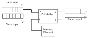
The problem statement, all variables and given/known data My homework is to design a Serial Adder in Verilog using a shift register module, a full adder module, and a D Flip-Flop module. I know my full adder and flip flop modules are correct, but I am not so sure about my shift register. The shift register is 8 bits: Inputs for the shift register are: Si, CLK, Reset Outputs for the shift register are: So, D7 through D0 (one for each bit of the register) Also, if anyone can give me a hint as to how I can approach designing a test bench would be extremely helpful. The attempt at a solution. Serial Communicator Mecanique Rationnelle.
Multisim Free Trial For Mac. Design of Serial IN - Serial OUT Shift Register using D Flip Flop (Structural Modeling Style).
